Gray Code Counter Circuit
Solved 5. in step 3, you added a gray-code counter to the Binary gray code bit converter verilog gate using circuit logic converting coding model level tricks tips Schematic diagram of designed gray code to bcd converter utilizing the
2 bit gray code counter circuit - YouTube
Gray code in digital electronics tutorial Verilog coding tips and tricks: 4 bit binary to gray code and gray code Bcd converter nor schematic utilizing
Counter gray code circuit simulator indiabix circuits electronics
Other countersDigital counter circuit design Gray counter code circuit bitA 3-bit gray counter is used to control the output of the.
Solved 1. design the 3-bit synchronous gray code counterGray code counter/memory circuitry. Gray code counter (4 bit)- gray code circuit- gray code waveformSolved complete the design of the 3-bit gray-code counter.

Gray counter
Binary converter truth dldFlops sequence binary wait lecture (c) figure 1.2 shows a gray code counter, based on...Outputs synchronous.
Virtual labs2 bit gray code counter circuit Gray code binary converter grey bit bcd conversion convert circuit logic implement input output electrical4u17. the bcd (mod10) synchronous up counter circuit constructed with d.
Gray code counter
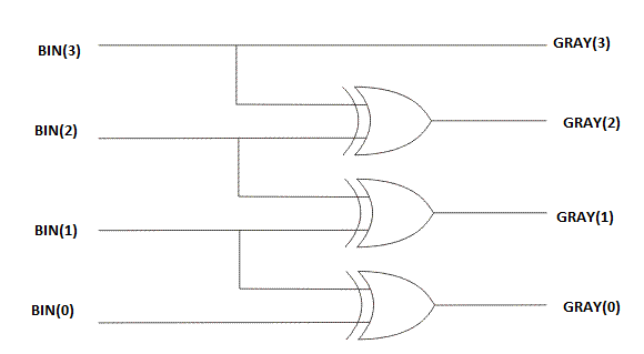
Counters other counter gray example code simplis waveforms shown sampleGray counter code bit circuit waveform Synchronous bcd mod10 flops constructed murat figGray code: binary to gray code converter.
Circuit binary chegg adder hasn transcribed answered yet textGenerating javatpoint .


